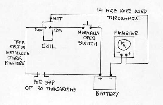
Current Flow – the circuit below is used to measure current flow when the coil is discharging:

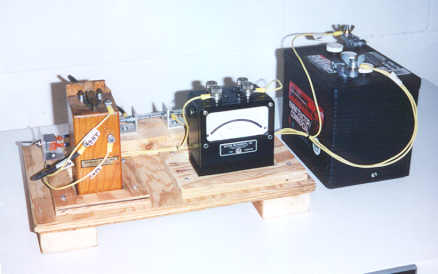
The photo below is my realization of the above circuit. From the left, the switch, coil, spark gap, ammeter and 6V battery.

You’ll need an analog ammeter with a range of 1A or 2A. I bought mine on eBay for $10. The air gap mimics the spark plug and thus the gap is the same as a normal plug gap. The section between the air gap and the plug terminal on the coil should be metal core spark plug wire, everything else can be 14 gauge wire. When the switch is closed the coil discharges and the current flow can be measured on the ammeter. Spec is 0.96 Amps. I’ve had coils show up to 5A flow, which is not good for the coil – shortens the life of it. Also, if you are running off a dry cell battery you will use it up faster with a high current draw.
First make sure that the points on the coil have been cleaned and set as described on the NARCOA website. Then put the coil in the circuit and test it. You can adjust the current flow by tapping on the rear of the lower bridge. Tap ahead of the mounting screws to lower the current flow, tap behind the mounting screws to increase current flow. I set mine at 1 Amp.
Internal Resistances – a good multi-meter is the tool for this job. I bought a new analog multi-meter for $20 on eBay. Measure resistances between the coil terminals, They should be:
Plug to Common = 3.11 KOhms
Battery to Common = 0.5 to 0.6 Ohms
Battery to Plug = 3.11 KOhms
Passing these tests does not guarantee that your coil will work perfectly but it does have a basic level of health. I’d like to acknowledge Bruce Pierce, the true coil expert who told me all the above information.
Last Edited 28 January, 2018